238 NAVIGATIONAL COMPASSES
tubular shaft R carries a group of slip rings against which press brushes for transmitting currents to the various electric devices attached to the phantom and to the sensitive element.
Three of the electric conductors for the operation of the sensitive element are within the tubular shaft projecting downward from the phantom and terminating in three pins near the center of the supporting globe. One pin is central and rests in a conical
cavity filled with mercury in a block of insulating material fastened to the supporting globe at its center. The other two pins dip into annular grooves filled with mercury, in the same block.
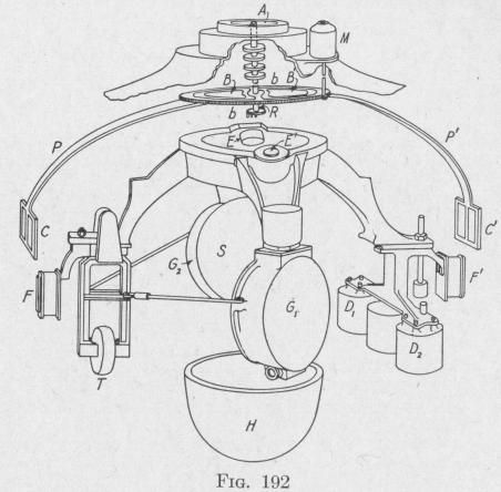
143. The Follow-Up System. - There is no mechanical connection between the compass card and the sensitive element. When the north-south line of the card becomes out of the meridian plane, it is brought into line with the meridian axis of the sensitive element by a reversible motor M controlled by an alternating current induced in two pairs of coils B, B', C, C', Fig..192, attached to the phantom. This induced current is due to rapidly changing magnetic fields set up by four alternating current magnets, E, E', F, F', attached to the sensitive element.
The turns of the follow-up coils B and B' are in a horizontal plane above two alternating current magnets E and E' that project upward from the top of the sensitive element. The two coils
THE ARMA GYRO-COMPASS 239
are wound in opposite directions. The turns of another pair of follow-up coils C, C' are wound in opposite directions in a vertical plane and normally are in front of horizontal alternating current magnets F and F'.
As shown in Fig. 193, a 120-volt, 60-cycle current energizes the primaries of two transformers, the secondaries of which are connected to the four alternating current magnets E, E', F, F' fastened to the sensitive element. Current from the same line is rectified and led to the mid-point of the field coils of the follow-up motor. The amplifying and rectifying circuit consists of three tripleelectrode vacuum tubes with the necessary transformer, condenser and resistances. In the diagram is shown an extra set of three tubes to guard against interruption of the operation of the system in case a tube should fail. In the subsequent description, the tube shown at the left end of each set will be called the " input tube " of that set, and the other tubes of each set will be called the first and the second " output " tubes, respectively. A 110volt direct current energizes the armature of the reversible followup motor and also the plate circuit of the input amplifying tubes.
The field coils of the follow-up motor are wound in opposite directions so that, if no current traverses them except the rectified current from the alternating current supply line, the two field pole strengths will be equal and of the same sign. Under this condition there will be zero torque tending to rotate the armature.
The current induced in the follow-up control coils, after being rectified and amplified, is superposed on the rectified current in
the follow-up motor field coils from the alternating supply line.
The follow-up control coils are connected in the grid circuit of the
input tube. The plate circuit includes the primary windings
of the interstage transformers. When the ship changes course, an
alternating electromotive force is induced in the follow-up con
trol coil connected to the grid circuit. This results in an alter
nating characteristic being impressed on the direct current flowing
in the plate circuit and an alternating electromotive force being
induced in the interstage transformer secondaries. These sec
ondary windings are connected with the circuit in such a manner
that the grid of one output tube becomes more positive with respect
to its filament at a given instant, and the grid of the other tube
becomes more negative. Thus the current in one follow-up
motor field coil will be strengthened and the current in the other
field weakened. Consequently the armatures will rotate and