250 NAVIGATIONAL COMPASSES
amplitude of a degree or two, thereby avoiding any chance for the phantom to stick.
The position of the north-south line of the compass card relative to the lubber line is transmitted to the course recorder, and to repeater compasses, by means of a transmitter commutator as in the case of other gyro-compasses.
150. Damping. - Damping of the oscillations of the spin-axle is effected by a method that causes the follow-up motor to absorb energy from the oscillating element.* The pin p, Fig. 197, which extends downward from the lower side of the gyro-casing projects
into a slot a in an arm attached to the phantom element. The
east side of the sensitive element is over
weighted so that the pin presses against the
west jaw of the slot. In Fig. 197, this over
weighting is indicated by a mass A on the east
side of the sensitive element.
The spin-axle of a pendulous gyroscope
tends to become parallel to the earth's axis,
with the direction of spin in the same sense
as the direction of rotation of the earth (Art.
106). It follows that when the spin-axle is
in equilibrium, the sense of rotation of the
gyro is clockwise as seen by an observer looking along the axle from south toward the north.
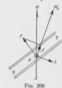
When the spin-axle of the Florentia gyro-compass oscillates, the phantom follows, in azimuth, the motion of the sensitive element. The north-south line of the compass card and the parallel slot are in the vertical plane of the spin-axle only when the sensitive element is in the resting position. At other times the vertical plane through the slot is slightly behind the vertical plane through the spin-axle. Consider the case when the north-seeking end of the spin-axle is east of and moving toward the meridian plane. In Fig. 200, the spin-velocity is represented by w,, the cross-section of the vertical pin by p, and the slot in the arm attached to the phantom element by q. Since the east side of the phantom is overbalanced, the east jaw of the slot pushes on the pin with a force represented by F. The component f of this force, parallel to the spin-axle, develops a torque on the sensitive element represented by L. As the spin-axle tends to set itself parallel to the torque
* Oscar Martienssen, "Eine neue Methode zur Dampfung der Schwingungen eines Kreiselkompasses," Physik. Zeit. 29, 295-300 (1928).
THE FLORENTIA GYRO-COMPASS
axis and with the direction of spin in the direction of the torque, it follows that the oscillation of the spin-axle is opposed. The pin p projecting downward from the gyro-casing is acted upon by forces that oppose both the motion of the spin-axle in azimuth and the motion in elevation. These oppositions to the motion of the spin-axle produce rapid damping of the vibration of the sensitive element.
If the sensitive element were overbalanced on the west side, the amplitude of successive swings of the spin-axle of the meridianseeking gyro would become greater and greater.
151. The Latitude and Meridian-Steaming Error Corrector. - Since the method employed to damp the vibration of the sensitive element of the Florentia gyro-compass opposes tilting of the axle
of the meridian-seeking gyro, this com
pass is subject to the latitude error (Art. 110). In common with all gyro-compasses it is subject to the meridiansteaming error (Art. 111). These two errors are corrected by a device that turns the phantom, relative to the spinaxle of the sensitive element, through such an angle that the north-south line of the compass card is free of both errors although the spin-axle of the sensitive element is not in the meridian plane.
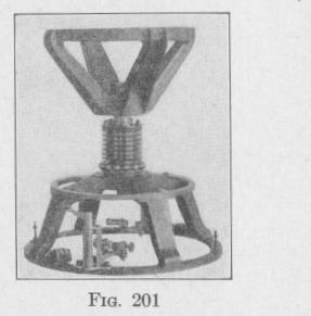
The pair of silver balls, Fig. 198, suspended from the top of the sensitive element, hang between two vertical plates, X, X', on one end of a crank, KK', Figs. 199 and 201, mounted on a frame attached to the phantom. A helical spring causes the upper end of the crank to press against the edge of a ring, Y, Figs. 197 and 199, fastened flat against the under side of the spider. The position of the ring can be adjusted so as to be eccentric to the vertical axis of the sensitive element and phantom. This eccentric ring constitutes a cosine cam similar to the one used on the Sperry Mark VI and Mark VIII gyro-compasses (Art. 123). The degree of eccentricity is controlled by the position of an arm on the upper face of the spider. This correction arm is graduated for latitude
and is capable of being moved over a flat scale carrying speed
curves.
When the correction arm is set for a given latitude, speed, and
course, the cam determines the proper position of the crank, and