72 MOTION OF A SPINNING BODY
suppose that at a certain latitude, the angular velocity of the gyroaxle relative to the earth, about a vertical axis, is w radians per second. Then motion of the gyro-axle in azimuth can be prevented by the application of a torque about the east-west axis that will produce a precessional velocity wp = w, given by the Second Law of Gyrodynamics:
L = w K3w3
where L is the torque expressed in pound-feet, KS is the moment of inertia of the gyro relative to the spin-axle expressed in slugfeet', and w3 is the spin-velocity expressed in radians per second.
If angular velocity of the spin-axle relative to the earth expressed in degrees per minute of time be represented by w', moment of inertia of the gyro relative to the spin-axle expressed in pound-feet2 be represented by KS', and spin-velocity expressed in revolutions per minute be represented by n, then the above equation may be written
L[= W/ KS' 2 an = 0.00000095 w' K3'n (66)
wKsws = (57.3)60 32.1 60
The vertical component, relative to the earth, of the angular velocity of the spin-axle of a freely suspended gyro in latitude X is
W = we sin X (68)
where we represents the angular velocity of the earth about the geographic axis.
Since the angular velocity of the earth is [360° = 24 X 601 _ 0.25° per minute of time,
w' = 0.25 sin X degrees per minute of time. (69)
42. The Sperry Directional Gyro. - The indications of a magnetic compass on an airplane can be relied upon only when the airplane is steady and moving in a straight course with constant speed. In taking a compass reading, the common practice is to steady the airplane in a straight course when near the desired compass heading and wait till the oscillations of the needle have become sufficiently small. To maintain a straight course either the ground must be visible or some gyroscopic turn-indicator must be available.
The various uncertainties in the indications of the magnetic compass have caused it to be largely displaced by the gyro-compass for naviaatina rn;rrine vessels, but the considerable weieht
MOTION OF A SPINNING BODY 73
and cost of the gyro-compass have prevented its adoption on airplanes. Many of the advantages of the gyro-compass for navigational purposes can be obtained by a simple gyroscopic device which is ckecked and reset at intervals against the indications of a magnetic compass.
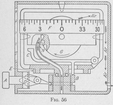
The Sperry Directional Gyro consists'of a freely suspended gyro G, Fig. 56, capable of spinning at a speed of some 12,000 revolutions per minute about an axis which normally is horizontal. At this speed of rotation, the spin-axle will maintain its direction in space within three degrees for a quarter hour. The spin of the gyro is maintained by air currents from two nozzles directed against
buckets cut in the edge of the gyro. The air flow is produced by a venturi as represented in Fig. 69, page 85. The path of air through the instrument is indicated by the feathered arrows.
In using the directional gyro as a navigational instrument, one method of procedure is first to put the airplane on the desired course by reference to the compass, then push in the setting knob A, thereby lifting the ring B and the lever C which, in turn, brings the spin-axle horizontal and locks it in that position. Now, the indicating card F of the instrument may be brought to the zero position by twisting the setting knob which, in turn, rotates the gear D, the azimuthal gear E and the attached indicating card. Pulling out the setting knob frees the gyro from all constraint. Then, the airplane can be kept in the desired course by steering so that the card of the direet,iona] avrn nnntiniiPa +n intlino+o --