208 NAVIGATIONAL COMPASSES
D2 are fixed to the spider. When the course of the ship changes, the ring and the gyro-axle preserve their direction in space whereas the rod AC and all the remainder of the correction device turns with the ship. When the ship with the rod AC turns relative to the ring R, the roller C moves either up or down as it follows the groove in the ring. When the course of the ship is inclined to the
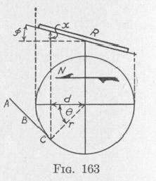
meridian, the roller is displaced vertically from the horizontal plane through the center of the ring by an amount x which now will be determined. Figure 163 represents the speed-corrector ring R, in elevation and in plan, when the course of the ship makes an angle 0 with the meridian. The inclination of the
plane of the corrector ring to the horizontal is (p. From the figure:
x = d tan 0= r cos 0 tan 0
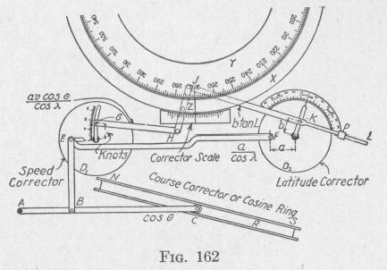
Since r tan 0 is constant, the above equation shows that the vertical displacement x varies directly with the cosine of the course of the ship. This displacement produces a corresponding displacement of the pin E fastened to the dial Dl.
A slot in the arc of a circle extends from
the center to near the edge of the speed-corrector dial Dl. The radius of the arc equals the distance between the two pins at the ends of the rod GH. When the speed corrector dial is rotated from the position shown in the diagram, the rod GH and the pin Z are moved along. The amount of displacement of the lubber ring thereby produced depends upon the distance v of the pin G
THE SPERRY GYRO-COMPASS 209
from the center of the dial D1. After the pin G has been clamped at the position corresponding to the speed v of the ship, the lubber ring will be displaced automatically by the amount required to allow for the quantity v in (130). Figure 162 is for a due westerly course. In this case there is zero correction for speed.
The pin E can move freely along the radial slit in the speed corrector dial. When the course of the ship is in the east-west line, the slot is horizontal as shown in the diagram. The position of the pin E in this slot is determined by the position of the pin F in the latitude-corrector dial D2. The distance of the pin F from the center of the latitude corrector dial is made proportional to the constant a in (130). The length of the rod EF equals the distance between the centers of the two dials. When the latitude corrector dial is set for zero latitude, the pins E and F are on the
straight line through the centers of the two dials. When the index is placed opposite the number representing the latitude of the ship, this arrangement makes allowance for the quantity a in
cos A
(130).
One end of the rod JL can slide in a fixed guide
P. This rod is fastened to the latitude-correction dial D2 by means of a pin and clamp K that permit rotation of the dial. The distance of the pin from the center of the dial is made propor
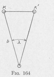
tional to the constant b in (130). If while the end H of the rod HJ remains fixed, the index of the latitude correction dial be set at the number corresponding to the latitude X of the ship, that is the clamp K moved to a new position K', then the edge of the lubber ring will be moved from the zero position through a distance proportional to KK'[= b tan X], Fig. 164. Thus proper allowance would be made for the second term in the right member of (130).
The speed and latitude corrector used on the Sperry gyrocompass Mark VI and VIII is much simpler in design than that just described. Two blocks, xx', Fig. 165, are attached to the lubber ring. The other part of the device, NK, is attached to the spider. The two parts are connected by a stud Z projecting from a nut that can be moved back and forth by means of the knurled headed screw Y. The face of the nut is marked off into divisions representing latitudes. By setting the division corre