212 NAVIGATIONAL COMPASSES
125. The Automatic Ballistic Damping Error Eliminator. - The Mark X gyro-compass is provided with an automatic damping eliminator which moves the pin e, Figs. 152 and 158, to a position vertically below the center of mass of the gyro-wheel when the ship has made a turn of as much as 15 degrees. Thereafter there is zero damping. The operation of the device is as follows: While the ship is making a turn, the compass binnacle with the attached spider element turns with respect to the phantom element and the gyro-axle. The large azimuth gear attached to the phantom element is in mesh with a small pinion attached to the spider element. The gear ratio is 3500 : 1. The pinion is connected to a shaft on which is mounted a group of three balls attached to three springs and a collar capable of sliding along the shaft. When the shaft and balls rotate, the balls fly outward thereby moving the collar along the shaft. When the ship is turned rapidly through an angle as great as 15 degrees, the sliding collar closes the electric circuit of a magnet which then moves the eccentric pin to a position vertically below the center of mass of the gyro-wheel. The damping now ceases and further ballistic damping error is prevented. When the turning of the ship ceases, the ball governor ceases to rotate, the electric circuit to the eliminator magnet is broken, the eccentric pin returns to its normal position and damping is renewed.
126. Avoidance of the Quadrantal or Rolling Error. - The sensitive element of the Sperry mercury ballistic gyro-compass is non-pendulous both when the mercury ballistic is in position and when it is detached. So long as the spin-axle is horizontal, all solid masses are balanced with respect to the horizontal axis. Forces due to rolling or pitching tend to accelerate these solid masses but they also will be balanced, and, consequently will produce zero deflection of the spin-axle. However, the meridian component of forces due to rolling or pitching will cause mercury to flow from one reservoir to the other, thereby causing the center of mass of the sensitive element to move to one side of the vertical line through the point of support. The oscillation of the mercury causes the sensitive element to act like a pendulum and to have a quadrantal error. By adding a small mass of metal to the top of each mercury reservoir, the sensitive element is made slightly anti-pendulous or top-heavy, thereby diminishing the quadrantal error produced at the end of each roll or pitch.
The dimensions of the apparatus are so selected that there is a
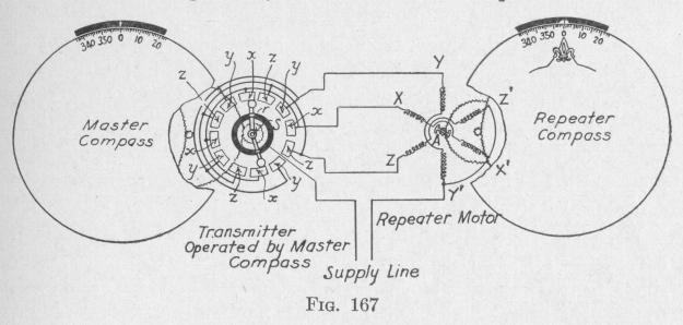
meridian is properly indicated. The master compass gives true headings but not true bearings. The angle which any horizontal line through the compass makes with the meridian plane equals the angle between the given line and the gyro-axle plus the angle through which the lubber line is shifted from its zero position. The sum of these two angles is the bearing of any object on the given line. The addition of these two angles is made automatically by a repeater system consisting of a transmitter T, Figs. 155 and 156. The transmitter is electrically connected to repeater cornpasses, course recorder, automatic pilot, radio direction finder or other devices situated at convenient places on the ship.
The transmitter of the Mark VI and Mark VIII models is represented diagrammatically in the left side of Fig. 167. It consists of a collector ring r, twelve terminal blocks x, y, z, arranged in a circle concentric with the collector ring, and a contactmaking transmitter arm capable of rotating about the central shaft. The transmitter arm is bent. The shaft s about which the arm rotates is at the elbow. On each end of the transmitter arm
THE SPERRY GYRO-COMPASS 213
phase difference of nearly one-quarter period between the oscillation of the sensitive element and the mercury from one reservoir to the other. As the residual slight deflections are not cumulative, they produce zero resultant deflection of the spin-axis.
127. The Repeater System. - The latitude error and the meridian-steaming error produce a deflection of the gyro-axle out of the meridian plane (Arts. 110 and 111). It follows that the card of the master compass does not give true directions relative to the meridian. When, however, the lubber line is shifted relative to the compass card through an angle equal to the latitude and meridian-steaming errors, the course of the ship relative to the