220 NAVIGATIONAL COMPASSES
sidered, the resting position of the spin-axle will be in the meridian plane.
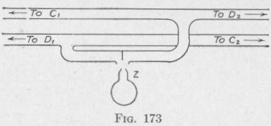
We have described the Brown damping device as though there were two air-boxes and air-blast nozzles, one of each for the control bottles and one for the damping bottles. In fact, however, the control bottles and the damping bottles are piped to a single
air-box, Fig. 172. The air-box is shown in detail in Fig. 173. The pipes are joined to the north working and to the north damping bottles, and to the south working and south damping bottles as indicated.
130. Absence of Latitude Error. - In northern latitudes, the north-seeking end of the gyro-axle will have a resting position above the horizontal plane through the center of the gyro-wheel. In southern latitudes, it will have a resting position below the horizontal. The natural tilt of the spin-axle is the amount required 'to cause precession at the rate at which the meridian is turning, that is the amount required to cause the axle to precess into the resting position after it has been displaced from that position. If the torque due to the pendulousness of the gyro-compass be small, the spin-axle will have the same resting position that it would have if the pendulousness were greater, but the speed with which the spin-axle precesses will be slower.
The method employed to damp the vibrations of the Brown gyrocompass is equivalent to a diminution of the degree of pendulousness of the gyro-system while it is oscillating through the meridian plane. It does not oppose the tilt of the gyro-axle required to precess the gyro-axle to the normal resting position. It follows that the Brown gyro-compass is without latitude error (Art. 110).
131. The Meridian-Steaming Error. - Every gyro-compass is subject to an error depending upon the meridian component of the velocity of the ship (Art. 111). No means are provided for correcting the indication of the Brown master gyro-compass, but the meridian-steaming error is allowed for in the repeater compasses
THE BROWN GYRO-COMPASS 22
by an eccentric mounting of the repeater cards. The proper degree of eccentricity in the mounting of the repeater cards is made by setting dials for the given latitude, speed, and course.
132. The Repeater System. - The pendulous system of the Brown gyro-compass, Type A, is shown in Figs. 168 and 174. The gyro-wheel, gyro-casing with the attached two control bottles and the two damping bottles, the vertical supporting ring R and the attached compass card C, constitute the sensitive element. The outer frame F carrying the lubber ring L and the motor-driven oil
pump P hangs on the Cardan rings of the binnacle and turns with the ship.
The angle between the lubber
line and the north-south line of the compass card is to be transmitted to and indicated by the repeater compasses, course recorder and other repeater devices. A horizontal gear ring, A, Fig. 168, of about the same diameter as the compass card, is mounted on the outer frame concentric with the lubber ring.
The angle indicated by the repeaters is to be the angle between the lubber line and an index line on the gear ring when this index line is parallel to the north-south line of the compass card. The gear ring A can be rotated about a vertical axis by a reversible motor M fastened to the outer frame. Frictionless contact between the sensitive element and the gear ring is effected by an air-blast from the gyro-casing against two plungers of a pneumatic electric contact maker.
The gyro-casing is supported by two hollow trunnions carried by knife-edges on the vertical ring. An air-blast produced by the rotating gyro-wheel passes through one of these trunnions, emerges from a nozzle fixed to the vertical ring and enters the air box connected to the control and to the damping bottles. Another air-blast traverses the other trunnion, emerges from a second nozzle B attached to the vertical ring and blows against two adjacent plungers of the pneumatic electric contact maker D fastened to the lower face of the follow-up gear-ring. The two plungers are connected to a rocking arm that makes an electric contact causing