76 MOTION OF A SPINNING BODY
developing a torque on the suspended system. At the instant represented in the figure, this frictional torque is represented by Lf. At all times the torque due to friction will be in the direction opposite to the precession wp. It follows, from law (d), Art. 40, that the suspended system is acted upon by a torque in the same direction as the gravitational torque L. Consequently, the suspended system precesses so as to hang more nearly vertical.
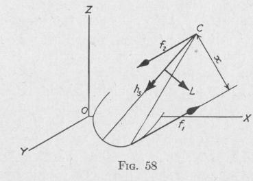
45. The Effect on the Direction of the Spin-Axis of a Top Produced by Friction at the Peg. - Figure 58 represents the rounded
peg of a top that is spinning about an axis which is inclined to the vertical and is in the vertical plane XZ. The center of mass of the top is at C.
Let h, represent the angular momentum of the top relative to the spin-axis. The force of friction f, at the point of contact of the
peg with the ground is shown parallel to the 0 Y axis and is directed away from the reader. An equal parallel force f2 acts in the opposite direction at the center of mass C. These two forces constitute a force couple having a lever arm x. The moment of this couple is about an axis in the vertical plane and is in the direction indicated by L.
Since the spin-axis tends to set itself parallel to and in the same direction as the torque-axis, it follows that hs turns about an axis parallel to YO in the counter-clockwise direction as viewed by the reader. As h, becomes more nearly vertical, x and therefore L decreases in value.
If the spin-axis were inclined to the left of the vertical, the direction of the torque due to friction would be in the direction opposite that represented in the figure, and the spin-axis would tend to become vertical as before.
Thus, on account of the friction between the ground and the rounded peg of a spinning top, the spin-axis of the top tends to become vertical. Owing to this effect, the upper end of the precessing axis of the top traces a converging spiral.
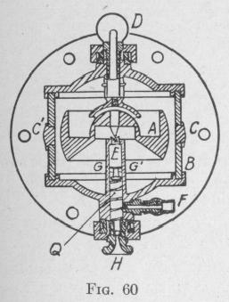
46. The Bonneau Airplane Inclinometer. - There is great need of an instrument that will furnish a line which will remain truly
MOTION OF A SPINNING BODY 77
vertical when on a ship or airplane subject to large linear or angular accelerations. The Bonneau inclinometer* is a top having a spherical peg the center of which coincides with the center of gravity of the top, Figs. 59 and 60. The peg stands in a spherical cavity of less curvature. The top is free of gravitational torque and precessional 9 / -,
1' 1911 F,
motion. Centripetal and other lateral forces
do not deflect the spin-axle unless they dis
place the pivot in its bearing. If such a .
displacement occurs, the rounded support- FIG. 59 ing peg accelerates any precessional velocity
thereby causing the spin-axle to assume a practically vertical position (Art. 45). The top is maintained in rotation by two streams of air impinging on short blades cut in the periphery. The driving air currents are produced by the motion of the airplane through the air.
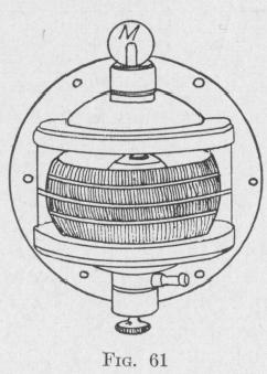
In one model, there are two parallel circular stripes about the periphery of the top and another similar stripe about the cylin
drical glass housing, Fig. 61. When the airplane is horizontal, th stripe on the housing is parallel to the two stripes on the top.
In another model, the indication is made by a light pointer fast ened to the top coaxially with the spin-axis. On the spheric~ cover glass over the top there are circles and radial lines by mean of which the observer can read the inclination of the housing t the vertical gyro-axle.
* U. S. Patent. Bonneau. No. 1435580. 19