82 MOTION OF A SPINNING BODY
axis through M perpendicular to the plane of the axis of figure and the trajectory, tending to raise the nose of the projectile. The angular momentum of the projectile about the axis of figure is so great, however, that this torque produces negligible deflection about the torque-axis but does produce a precessional velocity about an axis perpendicular to the torque-axis and the spin-axis.
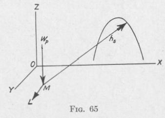
In Fig. 65, the angular momentum h5, the torque L, and the pre
cessional velocity wp are represented by directed lines. Since the
spin-axis tends to set itself parallel to the torque-axis, with the
direction of spin in the direction of the torque, it follows that,
owing to air pressure on the under side of the nose of the projectile,
the nose is deflected to the right along a line perpendicular to the plane containing the trajectory and the spin-axis.
Again, the friction of air against the lower side of the nose of the spinning projectile produces a torque opposing spinning, about an axis
CD, Fig. 64, nearly parallel to the plane containing the trajec
tory and the spin-axis. On account of this torque, the spin-axis
AB precesses about an axis perpendicular to the plane of the
spin-axis and torque-axis, tending to become parallel with and in
the same direction as the torque-axis CD. Thus, the nose of the
projectile is lowered and the spin-axis is made more nearly tangent
to the trajectory.
The result of the drift and the drop is a rotation of the axis of the projectile in the clockwise direction about the trajectory. The rotation of the axis of the projectile would be counter-clockwise if either the direction of spin were counter-clockwise or the center of effort were behind the center of mass.*
49. The Effect of Revolving a Non-Pendulous Gyroscope with Two Degrees of Rotational Freedom about the Axis of the Suppressed Rotational Freedom. - A gyroscope in which the center of mass of the gyro and supporting frame is at the intersection of the axes of rotation is said to be non-pendulous. If the center of mass is below the intersection of the axes of rotation, the gyroscope
* For a fuller discussion see Crantz, Lehrbuch der Ballistik, 1925; Hermann,
MOTION OF A SPINNING BODY 8
is said to be pendulous; if it is above, the gyroscope is said to be
antipendulous or top-heavy.
Experiment. - Clamp the middle ring of the gyroscope, Fig. 34,
so that rotation of this ring about the vertical axis is prevented.
As the gyro now can rotate about two axes perpendicular to one
another but not about a third perpendicular to the plane of the
other two, the gyro is said to have two degrees of rotational free
dom. Set the gyro spinning and place the gyroscope on a rotatable
platform. Rotate the platform in the clockwise direction about
the vertical axis. Observe that the spin-axle of
the gyro sets itself parallel to the vertical axis
with the direction of spin in the clockwise direc
tion. Now rotate the platform in the counter
clockwise direction. Observe that the gyro
turns over so that the spin-axle is again parallel
to the vertical axis, and the direction of spin is
in the counter-clockwise direction.
When the gyro-axle is revolved, a torque acts
upon the gyro relative to the axis about which rotation is suppressed. The spin-axis tends to set itself parallel to this torque axis, and with the direction of spin in the direction of the torque, according to the Second Law of Gyrodynamics (Art. 34).
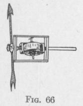
Experiment. - The gyro of Fig. 66, has but two degrees of rotational freedom. The arrow is fixed rigidly to the frame supporting the wheel so as always to be in the same direction as the gyro-axle. If a person holding the handle of the instrument horizontal rotates himself about one heel, the gyro-axle with the attached arrow will set itself vertical. When he turns about the heel in the opposite direction, the wheel with the attached arrow will turn a somersault. In each case the
axle becomes parallel to the axis of rotation of the
entire instrument and with the spin of the wheel in the same di
rection as the rotation of the instrument.
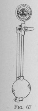
Experiment. - Figure 67 represents a knife-edge pendulum to
one end of which is attached a gyroscope in a frame that cannot
rotate about an axis parallel to the knife-edge. Set the pendulum
swinging and observe that the gyro-axle sets itself parallel to the
knife-edge and with the direction of spin in the same sense as the
angular valnrifv of fha „o„fli,1,,,» n l--4 4t,,. 1-r,. -a_-