98 MOTION OF A SPINNING BODY
outer gimbal ring is a horizontal disk having a cam on the edge. This cam comprises a rectangular part C, Fig. 82, concentric with the edge of the disk, and a spiral part c, like one turn of the square thread of a jackscrew. A light tappet, t, capable of angular motion about a vertical pivot, oscillates rapidly toward and away from the cam along the radius of the cam-disk parallel to the longitudinal axis of the torpedo. The tappet has two fingers at different levels.
Normally, that is when the torpedo is on a straight course, the axis of the torpedo and the radius of the cam-disk through the
center of the square part of the cam are parallel to the gyro spinaxle. In this case, when the tappet moves up to the cam-disk, the two fingers strike the square part C of the cam and the tappet will be turned till its axis is parallel to the radius of the cam-disk that goes through the center of the square part of the cam. This position of the tappet is preserved during the reverse stroke. On the reverse stroke, the arm of the tappet will move into the gap between the two pallets p and p', Fig. 81. Just as soon, however, as the torpedo axis departs slightly from parallelism to the gyro spin-axis, one finger of the oscillating tappet strikes the cam and the other strikes the edge of the disk. As the cam is farther from the center of the disk than is the edge of the disk, the tappet will be tilted to the left or right of the torpedo axis. On the reverse stroke, the arm of the tappet will strike one of the pallets p or p',
MOTION OF A SPINNING BODY 99
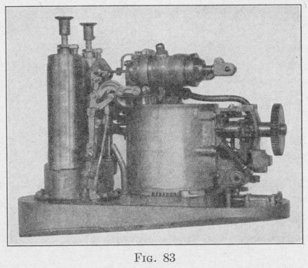
tilt the two connected elbow levers and move the valve rod v either forward or backward. The displacement of the valve rod allows compressed gas from the combustion pot to enter the steering motor E on one side of the piston or the other, thereby turning the vertical rudder either hard to port or hard to starboard. Figure 83 gives a view of the assembled control mechanism.
59. Method of Compensating the Effect of the Rotation of the Earth. - During the time that a torpedo is making a run of ten minutes, the earth rotates 2.5°. If the gyro-axle remains fixed in space, its direction relative to the earth changes by an amount that depends upon the latitude and also upon the direction in which the torpedo is moving. The deflection of the spin-axle in azimuth can be compensated by the application of a torque that will maintain a precessional velocity equal and opposite to the proper component of the angular velocity of the earth. The required torque is produced by the weight of a small nut that can be moved along a screw fastened to the inner gimbal ring and extending in the direction of the gyro-axle. To obtain the correct torque, the gyroscope is mounted on a stand, the gyro set spinning at the correct speed, and the position of the adjusting nut changed till the gyroaxle remains stationary in azimuth. This adjustment also compensates for any lack of balance of the gyroscope that would produce a precession.
The spin-velocity of a torpedo gyro is not constant throughout a long run. The precessional velocity due to any given torque varies inversely with the spin-velocity (57). Consequently, the adjusting nut is placed so that the mean precession of the gyro equals the angular velocity of the gyro-axle due to the rotation of the earth at the given place. If the adjustment is correct for a ten-minute run at a given latitude, then for a run of shorter duration, or at a place nearer the pole, the torpedo will be deflected to the right.
60. Devices for Changing the Course of a Torpedo. - Several methods have been devised for causing an automobile torpedo to make a turn of any predetermined angle and thereafter proceed along a straight course. The Leavitt* method of " angle fire " or " curved fire " is to turn the cam-disk from its zero position on the second frame of the gyroscope through the required angle in the proper direction. The rudder is thereby held hard over till it
* U. S. Patent. LP,.vitt. No 92.5710 1009