102 MOTION OF A SPINNING BODY
gyroscope. Fairchild and Morton* have devised an apparatus for this purpose that includes a gyroscope the axis of which continues to point toward the center of the earth. The gyroscope controls two motors without itself being acted upon by sufficient torque to disturb the direction of the spin-axle.
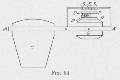
The camera C is fastened rigidly to one end of a frame AA', Fig. 84, capable of rotation about two horizontal axes, perpendicular to one another, through the point 0. The casing G of a gyro with vertical spin-axle is supported non-pendulously in gimbal rings on the other end of the frame. The gyro-casing carries a horizontal ring R capable of being turned about the spin-axle. Fast
ened to this ring is a threaded rod D in the direction of a radius of the ring. A mass m can be moved along this rod.
Suppose that the instrument is in the northern hemisphere, the spin-axle is vertical and the gyro is spinning in the clockwise direction as viewed from above. After a time, although the spin-axle will be pointing still in the same direction in space as before, it will be pointing to the east of the center of the earth because the earth has rotated meantime from the west toward the east. The direction of the spin-axle can be maintained vertical by precessing the spin-axle about a horizontal axis in the meridian plane of the earth, with an angular velocity equal to that of the earth and in the opposite direction. The required precessional velocity can be produced by the application of the proper torque about an eastwest axis. With the direction of spin as specified above, the desired torque is developed when the mass m is at the proper distance to the north of the spin-axle. By this device the spin-axle is caused to maintain a practically vertical position.
* U. S. Patents. Fairchild and Morton, No. 1559688, 1925; No. 1679354, 1928.
MOTION OF A SPINNING BODY 1
One method by which the gyro may be used to keep the camera axis pointing to the center of the earth involves the use of two motors controlled by currents induced by any motion of the camera relative to the gyro. One motor can turn the frame about an axis AA' and the other about a horizontal axis perpendicular to AA'. A flat coil P, with axis vertical, is fastened to the upper
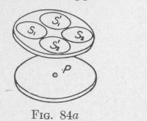
face of the gyro-casing. This is traversed by a high-frequency alternating current of a few milliamperes produced by the rotation of an armature forming part of the gyro. Four other flat coils with axes vertical are supported above the coil P by a bracket fastened to the frame. The five coils are represented in perspective in Fig. 84a.
The coils S, and S2 constitute part of a secondary circuit that includes a three-electrode vacuum tube, transformer, condensers, direct current motor and battery. The coils S,' and 82' constitute part of another secondary circuit. So long as the primary coil P is equally distant from the four secondary coils, zero electromotive force is induced in each secondary circuit and neither motor starts. This is the condition when the camera is vertical.
If the end A of the frame tilts upward, the system of four secondary coils becomes inclined to the horizontal plane of the coil P, Fig. 84a, coil P now is nearer S2 than to S, and it is equally distant from S,' and S2'. An electromotive force is being induced in S,S2 whereas zero electromotive force is being induced in Si S2'. The motor in the S,S2 circuit starts and tilts the frame till the plane of the secondary coils is parallel to the plane of the primary coil P, that is, till the camera axis becomes vertical.
In the same manner, if the frame becomes tilted about an axis AA', the distance between the primary coil and the two secondary coils Si and S2' becomes unequal. The motor in the Si S2' circuit starts and tilts the frame back till the camera axis is again vertical. The currents in the primary and secondary coils are so minute that these actions produce an inappreciable force on the gyro and therefore no precession.
64. Control of the Line of Sight of a Camera. - The camera, instead of being held vertical over the ground to be photographed, may be mounted rigidly along the fore-and-aft axis of the airplane and a vertical beam of light from the ground reflected into the lens system. This can be done by either a plane mirror or a totally refleetino nrism nleeed in front of the lens system. In order