126 THE GYROSCOPIC PENDULUM
will make a chart of the magnitudes and positions of all irregularities of the track. On the paper are drawn curves coordinating distance and time, distance and differences in the elevation of the two rails under the car as well as the positions and magnitudes of rail spreads and rail depressions.
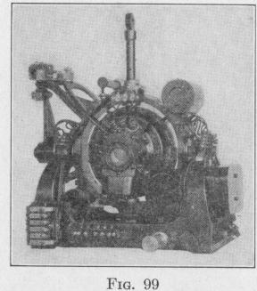
Differences in the elevation of the two rails are recorded by means
of a gyroscopic apparatus mounted on a table supported by one
of the car axles, Fig. 99. The function of the gyro is to furnish,
at any instant, a vertical plane parallel to the rails, with reference
to which can be measured any elevation of one rail above the other.
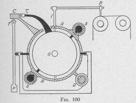
The gyro is mounted with the spin-axle normally parallel to the car axles. The gyro-casing is supported in a ring R, Fig. 100, which normally is vertical. The gyro-casing is capable of turning about a vertical axis, and the ring is capable of turning about a horizontal axis parallel to the rails. The center of gravity of the gyro and of all parts attached to it coincides with the intersection of these three axes. Hence,
a change in either the direction
or magnitude of the velocity of the car produces no torque on the
gyroscopic system and consequently no change in the direction
of the spin-axis in space.
When the car axle tilts from the horizontal, the frame of the gyroscope tilts with respect to the spin-axle, thereby causing a paper record roll to move under the pen p perpendicularly to the plane of the diagram.
For accurate indications, the indicator post I must be maintained in a vertical plane perpendicular to the normal position of the car axle. The indicator post is maintained in this vertical plane by means of a pendulum P and a pair of current-carrying solenoids SS. These solenoids are fastened to the ring R. Projecting into each solenoid is one end of a soft iron core having the other end fastened to the gyro-casing. When either of the solenoids is traversed by a current, the far end of its core is drawn inside the solenoid thereby producing a torque on the gyro-casing about a vertical axis.
GYRO-HORIZONTALS AND GYRO-VERTICALS 12
If, for any reason, the indicator post becomes deflected out of a vertical plane perpendicular to the car axle, that is, out of the plane of the diagram, Fig. 100, the contact arm C moves relative to a trolley wheel T on the upper end of the pendulum P. An electric circuit is thereby completed through one of the solenoids S, a torque, acts on the gyro-casing about the vertical axis, and the ring R precesses about a horizontal axis till the indicator rod is parallel to the pendulum.
Since the plane of vibration of the pendulum is perpendicular to the direction of motion of the car, no change in velocity of the
car while it is moving on a straight track will deflect the pendulum from the vertical. When, however, the car is moving around a curve, the pendulum bob will retreat from the center of the curve, thereby deflecting the pendulum from the vertical. Consequently, during the time that the car is going around a curve, the electric circuit controlled by the pendulum must be kept open. An arrangement of contacts automatically keeps the pendulum circuit open while the car is going around a curve. During this time, the direction of the spin-axle is fixed in space because the gyro is mounted so as to be free of any torque due to any change in either the direction or magnitude of the velocity of the car.
While the car is going around a curve, the spin-axle of the gyroscope tends to turn relative to the car about a vertical axis. This is due to the fixity in space of the spin-axle. Again, the friction of the pen on the paper produces a torque about the horizontal axis