214 NAVIGATIONAL COMPASSES
is a trolley which presses against the circle of contact blocks. At the elbow are brushes which press against the collector ring. The shaft s fastened to the transmitter arm is connected by a gear train to the azimuth gear of the compass. When the ship and the lubber ring turn with respect to the sensitive element, the transmitter arm rotates inside of the circle of terminal blocks.
Each repeater compass, course recorder or other auxiliary operated by the master compass has a repeater motor which is represented diagrammatically on the right side of Fig. 167. The motor has three pairs of poles and a soft iron armature A. When one pair of diametrically opposite poles is energized, the soft iron armature sets itself in line with that diameter, thereby rotating any compass card, course recorder or other auxiliary attached to the armature. When the transmitter arm rotates in the counterclockwise direction, contacts are made in the sequence x, y, z, x, y, etc., and the repeater armature rotates in the same direction. When the transmitter arm rotates in the clockwise direction, contacts are made in the sequence x, z, y, x, z, etc., and the repeater armature rotates. in the same direction.
With the transmitter arm in the position shown in the diagram, current goes from the direct current supply line to the collector ring r, to two x contact blocks, to the motor field coils XX' and back to the generator. The armature A sets itself in the direction XX'. If the transmitter arm rotates clockwise till one trolley is in contact with an x block while the other trolley is still in contact with a y block, then both the YY' field coil and the XX' field coil will be magnetized, and the armature A will set itself midway between them. Thus while the transmitter arm is making one revolution, the repeater armature makes one revolution in twelve steps.
The gear ratio between the repeater motor armature and the connected repeater compass card of the Mark VI and the Mark VIII Sperry gyro-compasses is 1 to 180. Consequently one revolution of the repeater motor armature rotates the connected repeater compass card two degrees. Therefore each electric impulse from the transmitter produces a rotation of the repeater compass card of one-twelfth of two degrees or ten minutes of angle. That is, a Mark V, Mark VI or Mark VIII gyro-compass repeater will indicate a change in the ship's course of five minutes of angle. The Mark X indicates a change in course of one-hundredth of a degree.
THE BROWN GYRO-COMPASS 215
Since the transmitter is attached to the lubber rind, the corrections made for latitude and velocity by shifting the lubber ring are included in the indications transmitted to the repeaters.
§4. The Brown Gyro-Compass
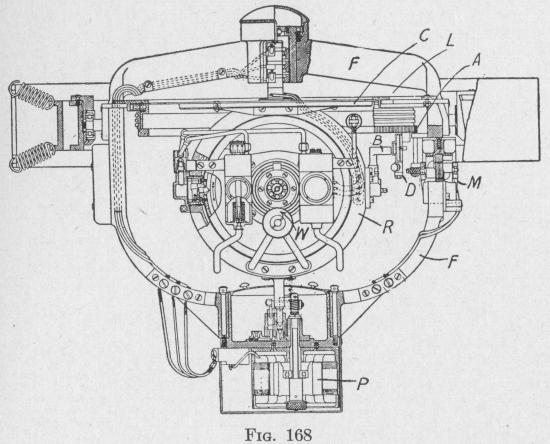
128. Production of the Meridian-Seeking Torque. - The Brown gyro-compass is an instrument developed in 1916, of the pendulous type, with a single gyro-wheel of 4.25 lb. spinning at
about 15,000 revolutions per minute.* The master compass, removed from the binnacle, is shown in Figs. 168 and 174. The gyro-casing is carried by horizontal trunnions mounted in bearings on a ring R, Figs. 169 and 174, which always is nearly vertical. The vertical ring is capable of turning about a vertical shaft extending above and below the ring. The entire sensitive element is carried by an outer frame suspended from the gimbal rings of the binnacle not shown in the figures. The sensitive element does not rest on a solid bearing but upon a column of oil at high pressure under the lower shaft. Friction about a vertical axis is reduced to almost zero by rapid pulsations of oil pressure which move the sensitive element up and down through an amplitude of
* Made by S. G. Brown, Ltd., London, England.