CHAPTER II
THE MOTION OF A SPINNING BODY UNDER THE
ACTION OF A TORQUE
29. Degrees of Freedom. - A locomotive, having a motion limited to motion back and forth along a straight track, is said to have one degree of freedom of translation. A block of ice on the surface of a frozen lake has two degrees of freedom of translation. A bird in the air can move in any direction and is said to have three degrees of freedom of translation or to be unconstrained with respect to linear motion.
A body that is rotating about an axis through the center of mass
of the body is said to be spinning. The flywheel of a stationary
engine is spinning about a fixed horizontal axis and is said to have
one degree of freedom of rotation. If the engine were on a turn
table capable of rotating about an axis perpendicular to the spin
axis, then the flywheel would be said to have two degrees of freedom
of rotation. If the flywheel were mounted so that the spin-axis
could rotate about two axes perpendicular to one another and also
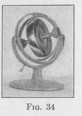
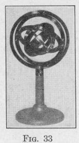
to the spin-axis, then the wheel would be said to hale three degrees of freedom of rotation or to be unconstrained with respect to rotation. A wheel mounted so as to be capable of rotation about five intersecting axes, Fig. 33, has three degrees of freedom of rotation, whatever may be the directions of the axes. A wheel mounted so as to be capable of rotation about three intersecting axes has three degrees of freedom of rotation except when all three axes are in the same plane, Fig. 34. When all three axes of the mounting are in the plane of the spin-axle, the wheel
cannot rotate about an axis perpendicular to that plane.
A ship's compass should stand upright however the ship may
either roll or pitch. The same is true of the oil lamps carried by
sailing vessels. Each should be free to rotate relative to the ship
about an athwartship axis and also about a fore-and-aft axis, that is,
should have two degrees of rotational freedom about two perpendic
MOTION OF A SPINNING BODY 45
ular horizontal axes. This result is attained by supporting the apparatus pendulously by two knife-edges on a ring which in turn is supported on two other knife-edges. The axes of the knife-edges intersect at right angles to one another. Such supporting rings are called gimbal rings or gimbals. The system of mounting is
often called Cardan's suspension and is in common use when a device must be supported so as to have two degrees of rotational freedom. The two inner rings of Fig. 34 constitute a Cardan suspension for the gyro-wheel. The gyro has a third degree of rotational freedom about the spin-axis.
By means of a rapidly spinning wheel mounted
so as to have three degrees of rotational freedom, Foucault in 1852 demonstrated the rota
tion of the earth. Since this apparatus exhibits the rotation of any body on which it is placed, Foucault called it a " gyroscope." If the direction of the spin-axle is changed, the moment of inertia of the wheel opposes the angular displacement. When it is desired to fix the attention on the property of the spinning wheel to oppose any change in the direction of the spin-axle, the instrument is called a "gyrostat." The spinning body is called the gyro-wheel or gyro. That part of physics dealing with the laws of motion of a spinning body under the action of a torque about an axis inclined to the spin-axle is called gyrodynamics. Any body or instrument that exhibits the laws of gyrodynamics may be called a gyroscope. The instruments represented in Figs. 33 and 34 are called Bohnenberger's gyroscope of five frames, and of three frames, respectively. By means of clamps, rotation of one or more frames can be prevented, thereby reducing the number of degrees of rotational freedom of the gyro to two or one.
30. The Effect on the Motion of a Spinning Body Produced by an External Torque. Experiment. - Attach a small mass m to the inner supporting frame of the gyroscope, Fig. 35, at a point near one end of the gyro-axle. Set the gyro-wheel spinning in the direction indicated in the figure by the arrow h3. At first, the spin-axle will oscillate slightly up and down and also to the right and left. Wait till the motion is steady and then observe that, although the weight of m produces a torque about the axis L, the dip of the gyro-axle about the torque-axis is not conspicuous.
Ohaervc fhat en lnna ac a Pnnsfanf PvfPrn,l fnrnua ante a)-i+ on