MOTION OF A SPINNING BODY
be a torque about a line normal to the plane of these axes given by (76).
When the spin-axle is perpendicular to the precession axis, 0 = 90°, sin 0 = 1, cos 0 = 0, and (76) becomes the Second Law of Gyrodynamics,
LB = KcwswZ = hswz (77)
When 0 = 0, sin 0 = 0, and the torque LB = 0.
The results of Arts. 52 and 53 apply to a top spinning about a
fixed point, the Griffin pulverizing mill, and many other cases.
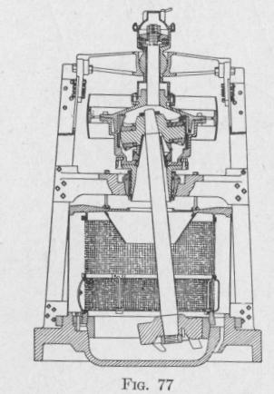
54. The Griffin Pulverizing Mill. - One form of mill for pul
verizing cement clinker, ores and other hard materials consists of
one or more massive rollers hanging vertically from the ends of a rotating arm. Owing to rotation, each roll presses against the inside of the enclosing pulverizing ring with a centrifugal force proportional to the square of the velocity of the roll relative to the pulverizing ring.
In the Griffin mill, a roll is hung by a universal joint from the end of a vertical shaft, Fig. 77. If the shaft with the rigidly attached roll be set rotating while its axis is vertical, the axis will remain vertical. If, however, the roll be moved over to the inside of the
ring, it will roll around the inner
face and push against the pulverizing ring with a centrifugal force
and also a force due to gyroscopic torque. Because of the re
sultant of these two actions the force against the pulverizing
ring is greater than it is in the case of the centrifugal roll mill.
Paddles on the lower side of the roll toss the material between
the roller and the pulverizing ring.
Problem. The roll of a Griffin pulverizing mill weighs 880 lb. and is 8 in. thick. The diameter of the upper face is somewhat greater than that of the lower face and the mean diameter is 23 in. The roll is fastened rigidly on the end of a shaft having a diameter of 5.75 in. and mass of 600 lb. The length of the shaft from the point of suspension to the upper face of the roll is 6 ft. The roll moves around the inside wall of a pulverizing ring having a diameter
ERRATUM
REPLACING THE SOLUTION OF THE PROBLEM, PP. 93-94
of 40 in. Find the force with which the roll presses against the pulverizing ring when the pulley is making 165 r.p.m.
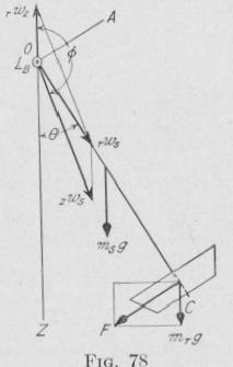
Solution. The torque acting upon the roll and shaft due to the rotation about the axis of the shaft, AC, Fig. 78, and the rotation of the axis of the
shaft about a fixed vertical axis, OZ, is given by
(76). Let
rn, = mass of the roll = 800 321 _ -7.4 slugs
.
600 lb.
,us = mass of the shaft = = 3'2.1 18.7 slugs
1, = length of roll = 0.(16 ft.
is = length of shaft = 6 ft.
d, = diameter of roll = 1.9 ft.
ds = diameter of shaft = 0.48 ft.
KA = moment of inertia of the shaft and roll
about an axis, 0.4, coinciding with the
diameter of one end, (24) and (27),
dr
KA-m(s(16+.)+nir(16+12+0"3,3,)
= 1)31 slug ft .''
Kc = moment of inertia of the shaft and roll about the axis of the shaft,
()C, (22),
= s nis(1s,2 + A rlirdr2 = s ('irsds2 + )ordr2) =e(18.7X0.23+27.4X3.6)=12.9 slug-ft.'
1.6ti 0.95
B = deflection of the roll shaft from the vertical = sin (--~; -
= fi° 40'.
,wz = angular velocity, about a ve tic l axis, of the azimuth plane th-ough the roll shaft and the point of suspension, relative to the pulve'nzing
ring. In (76) this is represented by 0z.
zws = angular velocity of the roil shaft relative to the rotating azimuth
plane. In (76) this is represented by via.
rup = angular velocity of the pulley about its axis, relative to the pul
verizing ring = 165 r.p.m.
The value of rwz now will he determined. If the azimuthal plane through the pulley shaft and roll shaft were not rotating, then -,,-hit-- the roll moves without slipping once around the inside of the pulve~izing ring, it would make R/r turns relative to the azimuthal plane. But while the roll makes one circuit of