96 MOTION OF A SPINNING BODS
Each hydrostat H has a diaphragm J at the lower end of a vertical cylinder. The under side is exposed to the pressure of the sea. Any desired pressure is applied to the upper side by adjusting the tension of a spiral spring that fills the vertical cylinder. If the torpedo sinks below the depth corresponding to the pressure for which the spring is set, the sea pressure pushes the diaphragm upward and the attached bell crank KLC rotates in the clockwise direction about a fixed shaft L thereby moving the valve rod DE in the direction indicated in the figure.
If the nose of the torpedo dips, the pendulum pulls the rod AB in the direction indicated by the adjacent arrow, and the valverod DE is pushed in the direction indicated in the figure.
57. The Conditions that Must Be Fulfilled by the Horizontal Steering Mechanism. - No device connected with the automobile torpedo has required so much study and experimentation as that employed to maintain a fixed course however the torpedo may be buffeted by waves. All practical devices depend upon the " rigidity of the spin-axis " in space of a gyro of three degrees of rotational freedom so long as the gyroscope is unacted upon by any outside torque.
The gyro must be mounted in gimbal rings. There must be a mechanism to keep the spin-axle pointing in a predetermined direction so long as the torpedo is within the launching tube. There must be a starting motor that will get the speed of the gyro up to a high value by the time the torpedo leaves the launching tube. There must be a device that will disconnect the locking device as soon as the torpedo enters the water and that will at that instant substitute for the starting motor another motor which will maintain the spin-velocity without interfering with the movement of the gyro-axle relative to the torpedo. A torque must be applied to the gyro that will produce a precessional velocity of the gyro-axle equal and opposite to the angular velocity of the gyroaxle relative to the earth (Art. 41).
While the torpedo is within the launching tube, the gyro of the locked gyroscope is speeded up to about 10,000 revolutions per minute by means of a separate turbine motor geared to the gyroaxle. The torpedo is projected by a charge of cordite. About the time the torpedo strikes the water, the gyroscope is unlocked, the starting motor is disconnected, and two streams of high pressure gas are directed tangentially into shallow buckets cut into the edge of the gyro.
If the torpedo axis is deflected from the direction it had when the gyroscope was unlocked, the angle between the torpedo axis and the gyro spin-axis is changed. The displacement of the gyro spinaxle relative to the torpedo axis is employed to operate a valve which controls the passage of compressed gas to one side or the other of the piston of a steering motor connected to the vertical rudders. In the transmission of the considerable force required to operate this valve, no appreciable torque must be applied to the gyroscope. Otherwise, the gyro-axle would be caused to precess and no longer remain in a fixed direction in space.
58. The Bliss-Leavitt Torpedo Steering Gear. - These cot ditions have been met in the Bliss-Leavitt torpedo steering meth, nism based on the patents of F. M. Leavitt and Wm. Dieter
The Bliss-Leavitt torpedo is used in the United States and other navies.
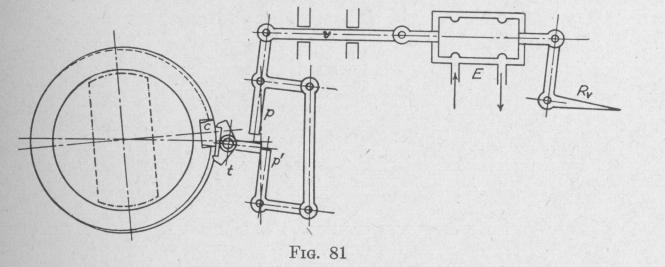
The operation of the device can be un
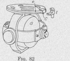
derstood from an inspection of Fig. 81, which is a simplified plan view of the mechanism for controlling the vertical rudders. The spin-axis of the gyro is horizontal, Fig. 82, the axis of rotation of the inner gimbal ring is horizontal and per
pendicular to the spin-axis; the axis of rotation of the out€ gimbal ring is vertical. Attached rigidly to the upper side of th
* U. S. Patents. Leavitt, No. 741683, 1903; No. 768291, 1904; Ni
795045, 1905; No. 785424, 1905; No. 814969, 1906; No. 901355, 1908
No. 925709,1909; No. 925710,1909; No. 1080116,1913; No. 1145025,19V
No. 1197134, 1916; No. 1291031, 1919.
Dieter, No. 1148154, 1915; No. 1233761, 1917; No. 1318980, 1919; N(
1402745. 1922• Nn iedne99 1097