202 NAVIGATIONAL COMPASSES
muth gear " Z, by means of which the phantom may be rotated so as to bring it into the plane of the vertical ring. The " mercury ballistic " B,B2 is fastened to a frame pivotted to this phantom. It is loosely connected to the gyro-casing by a pin e placed a little to the east of the vertical line through the center of mass of the suspended system.
The gyro-wheel, casing and vertical ring constitute the " sensitive element," Fig. 153, which is acted upon by a meridianseeking torque due to the rotation of the earth. The phantom element is shown in Fig. 154. The supporting spider is shown in Fig. 155. The complete gyro-compass, Mark VIII, removed from the binnacle is shown in Fig. 156. In this compass, the mercury
ballistic consists of two pairs of mercury reservoir B1Bi' and B2Bz , each pair connected by a small tube.
120. The Follow-Up System. - When the sensitive element becomes turned out of the meridian plane in either direction through an angle even so small as one-quarter of a degree, an electric contact is made which causes a small reversing motor, M, Fig. 155, to rotate the azimuth gear, Z, Fig. 154, through an equal angle in the same direction. Thus the phantom element follows the sensitive element, thereby preventing any appreciable twisting of the suspending wires. In this manner, the suspending wires never develop an appreciable torque in opposition to the meridian-seeking
torque acting on the compass. The follow-up system neutralizes
the effect of frictional forces that oppose motion about the vertical
axis.
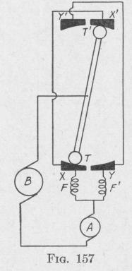
A pair of contactor plates, insulated from each other, is carried on each of the opposite sides of the phantom element, Q, Fig. 154. Lightly pressing against each pair of contractor plates is a small trolley wheel, T', Fig. 153, borne by the supporting ring. The electric connections of the follow-up system are shown in Fig. 157. In this figure, A represents the armature and FF' represent the field coils of a reversing motor fastened to the spider. The two pairs of contactor plates X Y and X' Y' are attached to the opposite sides of the phantom element, and the two trolleys TT' are attached to opposite sides of the sensitive element. Since the
THE SPERRY GYRO-COMPASS 203
motor is geared to the azimuth gear Z, Fig. 154, it is called the " azimuth motor." When the trolleys touch the contactor plates XX', as indicated in the diagram, current from B follows the course BTXFAB, and the motor armature together with the connected phantom element and system of contactor plates rotate in one direction. This rotation continues till the contactor plates YY' touch the trolleys TT'. Then the current follows the path BT'Y'F'AB. The direction of rotation of the azimuth motor and connected phantom element now is opposite that in the former case. The phantom element " hunts " back and forth through an angle of less than a degree about the sensitive element as midposition. This oscillation results in elimination of lag in the indications of the sensitive element.
121. The Method of Damping. - If there were no damping, the north-seeking end of the gyro-axle would move in an elliptical orbit in a plane perpendicular to the meridian plane, Fig. 137. The amplitude of oscillation will be damped if either the vertical or the horizontal component be reduced. If both components be reduced, the damping will be greater. In the Sperry gyro-compass both components are reduced by an arrangement that causes the major axis of the elliptical path traced by the end of the precessing spin-axle to be inclined to the horizontal. The arrangement consists in connecting the mercury ballistic loosely to the gyro-casing by means of a pin that is slightly to one side of the vertical line through the center of mass of the gyro-casing and wheel.
As shown in Art. 107, if the mercury ballistic were connected to the gyro-case by a pin vertically below the center of the gyrowheel, then the prolongation of the north-seeking end of the gyroaxle would trace on a vertical plane XZ, Fig. 158, a path which is an ellipse with major axis horizontal. Now we shall consider the effect of connecting the mercury ballistic to the gyro-case by a pin, e, to the east of the vertical through the center of the gyro. Suppose at some instant the spin-axle is horizontal and the northseeking end is directed toward a point a, Fig. 158, east of north. Owing to the rotation of the earth, mercury flows from the more easterly reservoirs to the more westerly (Art. 107). This causes the phantom P to press against the pin e and so produces a torque about an axis oL, perpendicular to the line oe. The torque produces a precession about the line oe, inclined to the vertical at an angle 0. Since the axis of precession is inclined to the vertical, the prolongation of the spin-axle will cross the meridian at a point b'