234 NAVIGATIONAL COMPASSES
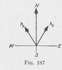
momentum of the system with respect to the north-south line, of
the value 2 h, cos 30° = 1.73 h5, Fig. 187. Along an east-west
line, the angular momentum of the western gyro is h, sin 30°,
while that of the eastern gyro is -h, sin 30°, the plus and minus
signs referring to the directions of spin. The opposition to roll
would be the same if the direction of spin of both gyros were re
versed. Thus the opposition to roll about a horizontal north
south axis is proportional to 2 hs sin 30° = hs, and the opposition
about an east-west line is proportional to 1.73 h,. These torques
are so great that when the system is given jerks by the rolling or
pitching of the ship, the period of the vibrations of the sensitive
element thereby produced is from five to ten
times as great as the period of the succession
of jerks. This great difference of period precludes forced resonant vibration of the gyro
element in tune with the vibration of the ship.
The jerks imparted to the pendulous system
by the rolling or pitching of the ship produce
a slight horizontal oscillation, but a negligible
tilting of the line from the point of support
to the center of mass of the pendulous system. Hence there is negligible quadrantal error. The centralizing device also opposes any rocking motion of the sensitive element.
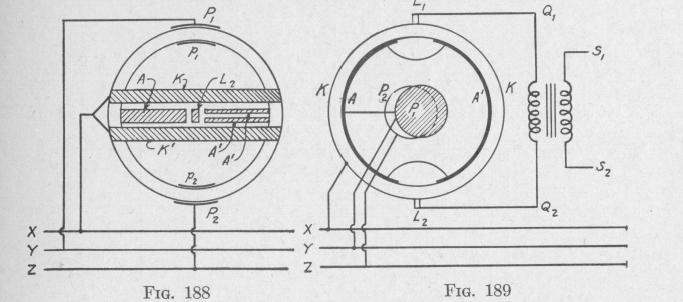
141. The Follow-Up Repeater System. - As the sensitive element does not touch the supporting system which carries the compass card, a follow-up device must be employed to maintain the compass card in constant relation to the sensitive element. The scheme employed comprises a reversing motor, M, Fig. 178, pinioned to a horizontal gear H fastened to the supporting system. The method of controlling the motor will be described by the aid of Figs. 188 and 189, which represent the gyro-globe and spherical shell in elevation, and in plan, respectively. In Fig. 188, the two electrodes KK' are shown as though they were separated by a greater distance than the two electrodes A', A'. In the actual apparatus, this is not the case.
When the sensitive element with spinning gyro-wheels is in equilibrium and the north-south line of the compass card is in the meridian, the two " follow-up " electrodes, L1, L2, on the inside of the spherical shell, face the centers of the corresponding vertical gaps between the equatorial bands on the gyro-globe. The three lines X, Y, Z, of a three-phase current circuit, are joined,
THE ANSCHUTZ GYRO-COMPASS 235
respectively, to the pair of equatorial electrodes on the inside of the outer spherical shell, to the upper polar electrode P, and to the lower polar electrode P2. The broad equatorial electrode A on the outside of the gyro-sphere and the two polar electrodes p,, p2 are joined to the three terminals of the two three-phase gyro-motors. The broad and the two narrow electrodes on the gyro-sphere are connected together.
At the instant when X is at a higher potential than Y and Z, current from X goes to KK'. There it divides, a part crosses the electrolyte to A, traverses the gyro-motors to pi, the electrolyte to P, and thence goes to the line Y. Meanwhile the other part crosses the electrolyte to A', passes to A, traverses the gyromotor to p,, the electrolyte to P, and thence to the line Y. These two paths are of different resistance.
With the spherical shell in some such position relative to the gyro-globe as that indicated in Figs. 188 and 189, the electromotive forces at L, and L2 will be in the same phase. When the spherical shell becomes slightly turned from this position, by the turning of the ship for example, the electromotive forces at the follow-up electrodes L, and L2 will be indifferent phase. The difference in phase will be reversed when the deflection of the spherical shell from the equilibrium position is reversed in direction. Thus, with any given phase difference between the lines X and Y, the wire Q1Q2 will be traversed by a current which in magnitude and in direction depends upon the angular displacement, from the equilibrium position, of the spherical shell relative to the gyro-globe. The variations of this current are caused to produce greater variations in the current of a three-electrode tube amplifying circuit.