THE ARMA GYRO-COMPASS 243
ship. Then, when the follow-up system turns the phantom, with the connected compass card, till the follow-up coils are in line with the corresponding control magnets, the compass card will show no error due to the course and speed of the ship although the meridian- seeking axis of the sensitive element is deflected from the me- ridian.
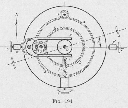
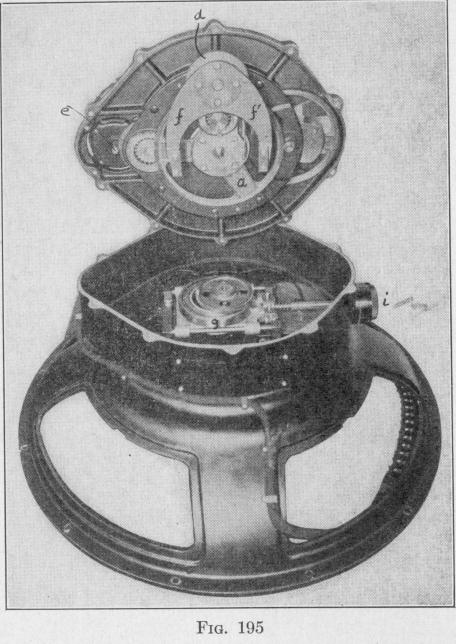
In Figs. 194 and 195 the circle a represents a gear fastened to the axle that carries the compass card; b, a gear fastened to the upper end of the vertical axle of the phantom element; c and d, two gears capable of turning about axles fastened to a plate at-
tached to the compass card; e, a pinion connecting the follow-up motor and the compass card. Fastened to the gear d is a fork f f'. If the prongs of the fork be moved nearer to or farther from e, the attached gear d is turned, and the connected phantom gear b is turned in the same direction. Such a displacement of the prongs of the fork can be produced by moving forward or back a nearly frictionless wheel g on the end of a screw h which is ro- tatable in a nut fastened to the compass frame.
Suppose that the meridian component of the ship's velocity is directed north. Then, the meridian seeking axis of the sensitive element will be deflected toward the west through an angle 51, depending upon the latitude, speed and course of the ship (124). Values of this angle for various conditions are given in tables. If no correction be made, the follow-up system will rotate the north-south line of the compass card through the same angle in the same direction.
Suppose, now, that the proper angle corresponding to 6, be set up on the dial i attached to the screw that moves the wheel g forward or back. For a north meridian component of ship's velocity, the dial-setting will turn the fork and the attached gear d counter-clockwise. The connected phantom gear b will be turned in the same direction, thereby rotating the line connecting the attached follow-up coils CC', Fig. 192, through the angle 61 in the
counter-clockwise direction away from the line connecting the control magnets FF. Since the line of action of the force with which the screw pushes against the fork passes through the axis of rotation of the compass card, this force is without effect on the indication of the compass card.
Before the dial was set, the line connecting the follow-up coils CC' on the phantom element coincided with the line connecting the
i