268 GYROSCOPIC STABILIZATION
GYROSCOPICALLY STABILIZED MONORAIL CARS 269
the spin-axle precesses in the counter-clockwise direction as indicated by the symbol w p. At the same time a heavy plumb-bob P pushes toward the reader the link A and the vertical arm of the bell crank B, thereby pushing downward the yoke C and the attached slotted segment D which is fastened to C by a pivot E. This action causes gear teeth on the upper edge of the segmental slot to engage with a gear on the shaft of the precession motor, thereby causing a thrust on the link F and an acceleration of the precession of the spin-axle. The accelerated precession develops a torque that tilts the car to the other side of the vertical. The precession of the spin-axle now reverses in direction, the plumbbob pulls on the bell crank in the opposite direction and the slotted segment disengages from the motor shaft. Immediately afterward the teeth on the lower edge of the segmental slot engage the gear on the motor shaft, thereby accelerating the present precession of the gyro spin-axle and developing a torque that again causes the car to tilt upward and beyond the vertical. Thus the car oscillates back and forth through the vertical, losing energy of vibration to the precession motor.
With this device, if the constants of the apparatus are of the proper values, the tilt produced when going around a curve is overcome to the same degree and in the same manner as a tilt due to wind pressure or any other cause when the car is moving along a straight level track.
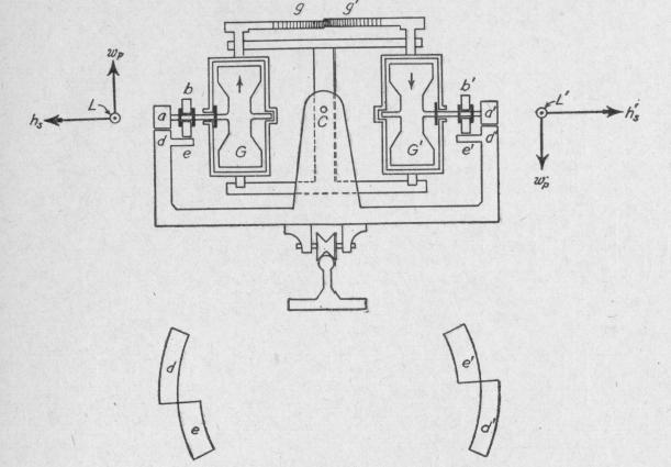
163. The Brennan Duogyro Monorail Car. - The first monorail car stabilized by two gyros, spinning in opposite directions about axes that normally are perpendicular to the track, was designed and built by Louis Brennan. The stabilizing system of Brennan's monorail car of 1905 consists of two gyros G and G', Fig. 218, spinning about axes that normally are horizontal and transverse to the car.* Each gyro is mounted in a casing capable of precessing about a vertical axis. The two casings are coupled together by two segments of gears g and g' so that at any instant the precessional velocities of the two gyros will be equal and in opposite directions. The coupled casings are mounted in a frame capable of rotation through a small angle about an axis through the center of gravity C of the gyro system and parallel to the track. The spinaxle of each gyro carries a rigidly attached roller a, a', and a loose roller b, b', respectively. At a short distance below each of the
* U. S. Patent. Brennan, No. 796893, 1905. Reveille, Dynamique des Solides (1923), pp. 398-406.
keyed rollers a and a', is a short shelf d and d', respectively. Under each of the loose rollers b, b', is a similar shelf e and e', respectively. A plan view of these shelves is shown in the lower part of the diagram. When the car floor is horizontal, the spin-axles are perpendicular to the rail, and each of the keyed rollers a and a' is almost in contact with the corresponding shelf d and d', respectively, at a point near one end of the shelf. The other shelves do not extend
Fra. 218
far enough to be under the loose rollers when the spin-axles are perpendicular to the rail.
Consider a monorail car with the gyros spinning in the directions indicated by hs and h,', respectively, Fig. 218. Suppose that for .any reason the car tilts to the left. This tilt produces a torque on the spin-axles of the two gyros in the directions indicated by L and L', respectively. The spin-axles precess in the directions indicated by wp and wp , respectively. The tilting of the car to the left. brings the shelf d' into contact with the keyed roller a'. Because of the friction between this roller and shelf, the roller advances along the shelf toward the reader, thereby accelerating the precession wp of the gyro G' and also accelerating the precession wp of the coupled gyro G. This acceleration is accompanied by a torque on the two gyros in the directions opposite the torques L and L' that produced the original precession (Art. 40). This