146 ANTI-ROLL DEVICES FOR SHIPS
within a cylindrical enclosure when the gyro precesses. The vanes are pierced by openings controlled by gates connected by an arm pivoted at B. The opposition to the flow of liquid through the openings depends upon the pressure of the gates against the vanes, and this depends upon the speed of precession of the gyro. The braking power is also adjustable by varying the leakage between the vanes and the walls of the enclosing cylinder. Two sections of the enclosing cylinder are hinged at H, and H2. By turning the screws S, or S2, these sections can be moved in or out, thereby changing the opposition offered to the motion of the vanes through the liquid. This adjustment would be made by hand and by an amount depending on the violence of the sea.
§3. The Active Type of Gyro Ship Stabilizer
92. The Effect on the Motion of a Swinging Pendulum Produced by an Attached Gyroscope : (b) When the Gyro-Wheel is Acted upon by an Outside Torque about an Axis Perpendicular
to the Spin-Axis and the Axis of Vibration of the Pendulum. Experiment. - The pendulum shown in Fig. 106 carries a gyro-wheel mounted so as to have two degrees of rotational freedom. The gyrowheel spins about an axis perpendicular to the axis of vibration of the pendulum and can rotate about a perpendicular
axis in the plane of vibration of the pendulum. In the present experiment, the latter axis may be either on, above, or below the center of gravity of the gyro-wheel and attached frame.
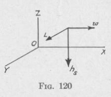
Hook one end of a stiff wire into an eyelet on the upper part of the frame that carries the gyro-wheel. While the pendulum is at rest, and the gyro-wheel spinning, pull the upper end of the gyroaxle out of the plane of the fixed outer frame. If the gyro-wheel is spinning in the clockwise direction as viewed from above, the pendulum bob will be given a slight motion to the right. This is in accord with the rule given in Art. 36. It is illustrated in Fig. 120, in which the line hs represents the angular momentum of the gyro-wheel about the spin-axis, w represents the angular velocity produced by the pull on the supporting frame, and L represents the gyroscopic torque thereby produced.
Pull the upper side of the gyro-frame every time the pendulum bob starts to move toward the right from the left end of its path,
THE ACTIVE TYPE OF GYRO SHIP STABILIZER 147
and push it every time the pendulum starts to move toward the left from the right end of its path. After a few oscillations, the pendulum will be vibrating with a considerable amplitude of swing. The building up of the amplitude of swing is due to the pendulum's being acted upon by a series of separate torques occurring with the same period as the natural period of the pendulum and always in the same direction as the vibration of the pendulum. This is an example of resonance (Art. 26).
Again, while the pendulum is swinging and the gyro-wheel is spinning clockwise as before, pull the upper end of the gyro-shaft every time the pendulum bob starts to move toward the left from the end of its path and push it every time the pendulum bob starts to move toward the right from the other end of its path. This procedure causes the pendulum vibrations to become reduced to zero after a few swings. In these two cases, observe that the direction of the torque applied to the gyro-wheel that increases the amplitude of vibration of the attached pendulum is opposite the direction of the precession of the gyro-axle produced by the motion of the pendulum, and that the direction of the torque applied to the gyro-wheel that damps the amplitude of vibration of the attached pendulum is the same as the direction of the precession of the gyro-axle produced by the motion of the pendulum. Consequently, in the case of a gyro-wheel having two degrees of rotational freedom mounted on a pendulum in such a manner that the gyro-axle, the axis of precession and the axis about which the pendulum vibrates are mutually perpendicular to one another, the amplitude of vibration of the pendulum will be increased if the gyroaxle be rotated by an outside torque in the direction opposite to the precession, whereas the amplitude of vibration of the pendulum will be decreased if the gyro-axle be rotated by an outside torque in the same direction as the precession.
In the first case, the periodic gyroscopic torque L, Fig. 120, acting on the pendulum is in phase with the angular velocity of the pendulum. The pendulum is absorbing energy at each vibration and the amplitude of vibration increases (Art. 65). In the second case, the periodic gyroscopic torque applied to the pendulum and the angular velocity of the pendulum are in opposite phase. The pendulum is losing energy at each vibration with a consequent diminution of the amplitude of vibration.
93. The Sperry Ship Stabilizer. - The Sperry ship stabilizer is designed to neutralize each roll increment soon after if,-, inenn-