148 ANTI-ROLL DEVICES FOR SHIPS
tion, thereby preventing the angle of roll becoming large. Its effectiveness is not dependent on the period of roll being constant. It applies the torque developed by the rotation of the spin-axle of a gyro of great moment of inertia, to the damping of the roll of a ship. The gyroscopic torque opposing roll is caused to be in the opposite phase to the velocity of roll. Consequently (Art. 65), the power absorbed from the rolling ship and the damping of roll thereby produced are maxima.
The Sperry ship stabilizer comprises two electrically driven gyroscopes, a powerful electromagnetic brake, an electric motor, two motor generators and a switchboard. One of the gyroscopes
is small and of three degrees of rotational freedom. The spinaxle precesses when the ship rolls through even such a small angle as a single degree. The other gyroscope is very large and of two degrees of rotational freedom.
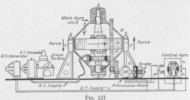
The arrangement of the parts of the device as seen on looking from the stern toward the bow of the vessel is as sketched in Fig. 121. The main or stabilizing gyro G, of great moment of inertia with respect to the vertical spin-axis is non-pendulous and is mounted so as to be capable of precession about an athwartship axis. This gyro is spun by alternating current supplied by a turbogenerator as indicated in the diagram. The spin-axle can be rotated forward or back about an athwartship axis by means of the " precession motor " M geared to the casing of the stabilizing gyro. The precession motor is operated by current from a direct current generator.
The direction of rotation of the precession motor and of the
THE ACTIVE TYPE OF GYRO SHIP STABILIZER 149
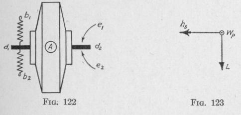
connected main gyro-casing is controlled by the small unconstrained gyro. The spin-axis of the control gyro is horizontal and athwartship, in a casing that can rotate about a vertical axis A, Fig. 122, perpendicular to the plane of the diagram. Centralizing springs b,b2 are attached to a pin dl at one side of the casing. Another pin d2 attached to the casing can play back and forth between two electric contacts e, and e2. When the pin d2 is in contact with e,, a current from the direct current generator rotates the precession motor M in one direction. When contact is made with e2, the armature of the precession motor rotates in the opposite direction. (In the elevation, Fig. 121, the contacts el and e2 are shown one above the other. Really, one is behind the other as indicated in the plan view, Fig. 122.)
The amount and speed of rotation of the spin-axle of the stabilizing gyro G are regulated by a magnetic brake on the armature shaft of the precession motor. This brake has strong springs that seize the armature shaft, thereby preventing rotation of the stabilizing gyro-axle except when the pressure of the springs is opposed by the pull of an electromagnet. The brake coils are in series with the precession motor. Consequently, when current is cut off the precession motor, the magnetic brake seizes the armature shaft and prevents rotation of the stabilizing gyro about the athwartship gudgeons FF, Fig. 121.
94. Operation of the Sperry Ship Stabilizer. - Suppose that the ship rolls to port even so little as one degree of angle, thereby producing on the horizontal spin-axle of the control gyro a torque L, about a horizontal fore-and-aft axis, Fig. 123. Then this axle will precess in the direction wp, thereby causing the pin d2 to move over and make contact with e,. This completes an electric circuit through the precession motor and magnetic brake. As the back electromotive force of the motor when at rest is very