210 NAVIGATIONAL COMPASSES
sponding to the latitude opposite the lubber line, the lubber line is shifted relative to the spider by an amount proportional to the quantity b tan X (130).
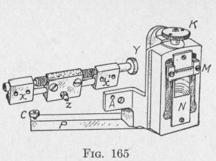
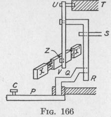
The course corrector cam consists of a circular groove in the under face of the azimuth gear, Z, Fig. 154. The groove is eccentric relative to the azimuth gear. In this groove fits a roller C on the end of a bent lever PQ, Figs. 165 and 166. The other end of the bent lever fits into the lower end of a vertical lever RT, Fig. 166, capable of rotation about a pin S. This pin can be moved up or down by means of a screw, K, Figs. 155 and 165, thereby changing the lever arm ST, Fig. 166. A displacement of the end T rotates the lever UV about a fixed pin U, thereby shifting the lubber ring attached to XX' by an amount which depends upon the lengths of the various lever arms. The lever PQ allows
for the quantity a cos 0. The allowance for cos X
is made by a
proper setting of the pin S. This setting is effected by adjusting the screw K, Fig. 165, until the correct latitude reading on the horizontal scale M is on the correct speed curve engraved on the face plate N, Figs. 156 and 165. The speed curves are obtained empirically.
By thus shifting the lubber line to the proper amount, the ship will point correctly but the compass will not. In taking bearings of heavenly bodies, or of points on the shore, it is necessary to know true directions. True directions can be Qbtained by means of a repeater compass electrically connected to a transmitting device mounted on the lubber ring of the master compass (Art. 127).
124. Avoidance of the Ballistic Deflection Error. - In the Sperry gyro-compass models designated Mark V, Mark VI, Mark VII and Mark VIII, the period of vibration of the sensitive ele-
THE SPERRY GYRO-COMPASS 211
ment required to avoid the ballistic deflection error is secured by regulating the amount of mercury that flows from one side of the sensitive element to the other.
The mercury ballistics of the Sperry Mark VI and Mark VIII gyro-compasses have two separate reservoirs B1, B2, Figs. 152, 156 and 158, on the north side of the phantom element, connected by two tubes to correspondingly situated reservoirs on the south side. The mass of mercury that can pass from one side to the other is such that the ballistic error is zero when the ship is at latitude 40° and is not great at any latitude.
The Mark V gyro-compass has a single mercury reservoir on the north side of the phantom element and another on the south side. These reservoirs are divided into compartments and provided with valves which can be adjusted to give four different masses of active mercury. With one weight of active mercury, the torque that opposes tilting is such that the ballistic error is very small at all latitudes between 0° and 35°; with another weight, the error is very small at all latitudes from 30° to 50°; with another weight, the error is very small at all latitudes from 45° to 62°; with another weight, the error is small at all latitudes from 60° to 70°; in each case the ballistic error is zero at the mean latitude.
The period of the Sperry gyro-compass models designated Mark IX, Mark X and Mark XI is adjusted to the value proper to any given latitude by changing the lever arms of the weights of the active liquid in the mercury ballistic. This result is accomplished by moving four mercury reservoirs to the proper distance from the vertical axis through the center of mass of the suspended system. Each pair of reservoirs is fastened on opposite ends of a jointed tube similar to the jointed gas-light brackets sometimes used over work benches. By means of a worm and gear provided with a divided scale the reservoirs can be moved to the position proper to the known latitude. This device can be recognized in the Frontispiece. Observe the horizontal shaft carrying a worm at each end, on the right-hand side of the sensitive element. Each worm engages in a horizontal gear to which is rigidly attached a cylindrical reservoir. The reservoir attached to the gear that engages with the worm on the left-hand end of this horizontal shaft is only partially obscured by the gear. Observe the small tube joining this reservoir with another on the left-hand side of the sensitive element,