80 MOTION OF A SPINNING BODY
airplane is in straight level flight with its present load. By the aid of standard turn indicator and rate-of-climb indicator, the pilot knows when the airplane is in straight level flight. Knowing the
normal position of the horizon bar, the pilot can use the Sperry
horizon to inform him of the altitude of his airplane during night
or blind flying when the invisibility of the actual horizon would
render flying difficult and often dangerous.
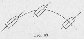
48. The Drift of a Projectile from a Rifled Gun. - If a pro
jectile fired from a gun were uninfluenced by any force except
its weight, the center of mass of the projectile would describe a parabola having a vertical axis (Ferry's General Physics, p. 68). If the bore of the gun were not rifled,
there would be no tendency for the projectile to rotate about any
axis. If the projectile were cylindrical, the axis would remain
parallel to the axis of the gun throughout the flight of the projec
tile, as represented in Fig. 63.
In the actual case, however, the projectile moves through air and is acted upon by air resistance, which profoundly modifies the motion. Air resistance lifts the nose of the projectile. If the bore of the gun were smooth, the nose of the projectile might be lifted to such an extent that the projectile would strike broadsideon or might tumble. For this reason, the projectiles used with smooth-bore guns are spherical. By rifling the bore of the gun, the projectile is given an angular velocity of spin about the long axis of as much as 3000 revolutions per second for infantry arms. The large projectiles of the coast artillery spin much more slowly, in some cases as slowly as 100 revolutions per second. The projectiles from American guns rotate in the clockwise direction as viewed from the gun. Owing to the " rigidity of the spin-axis," a spinning long projectile has a much greater range than if it were not spinning, but there is a lateral deflection. With projectiles of the same model, this lateral drift is to the right when the direction of spin is clockwise and to the left when the spin is counterclockwise. The amount of drift depends upon the shape and upon the angular momentum of the projectile about the spin-axis. The drift amounts to as much as one yard in a 1000-yard range and eleven yards in a 3000-yard range. Drifts as great as 2000 feet have been observed in a 20-mile range. Drift is caused by a
MOTION O 1 F A SPINNING BODY Sl
combination of the direct effects of air pressure and air friction, and by gyroscopic effects produced by torques developed by air resistance and air friction. There is no complete explanation of the observed facts of drift of projectiles, but it is probable that the following actions are important causes.
Due to the rotation of the earth, a body moving with linear velocity over the surface of the earth will be deflected, relative to an observer on the earth, out of its original path. Th&,vertical component of the linear velocity of a projectile is deflected westward when the projectile is ascending and is deflected eastward when descending. A body thrown vertically upward will fall west of the place of projection. The horizontal component of the linear velocity of a projectile is deflected to the right in north
ern latitudes and to the
left in southern latitudes. These deflections are not due to forces acting on the projectile but are due solely to the rotation of the body to which the linear velocity of the projectile is referred.
Consider a projectile spinning in the clockwise direction about the axis of figure. There is a force due to air friction opposing the spin. When the axis of the projectile is inclined to the trajectory, this air friction is greatest on the under side of the nose and the projectile " rolls off " toward the right. Since the friction is greater on the nose than on the rear end, the front end of the projectile rolls to the right more rapidly than the rear end. The wind now striking the left side of the projectile causes a drift to the right.
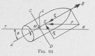
Again, suppose that the axis of figure of the projectile is inclined to the trajectory TR, at an angle 0, Fig. 64. The resultant air resistance is a force F parallel to the trajectory and applied at a point called the center of effort. Usually the shape of a projectile is so designed that the center of effort E is on the axis of figure and in advance of the center of mass M. Resolving F into two components, one parallel and one normal to the axis of the figure, we have FP = F cos 0 and Fn = F sin 0. The former component retards the motion of the projectile. The latter has a moment L about the center of mass, L = xF, = xF sin 0, where x represents the distance ME. This torque xF sin 0 acts about an